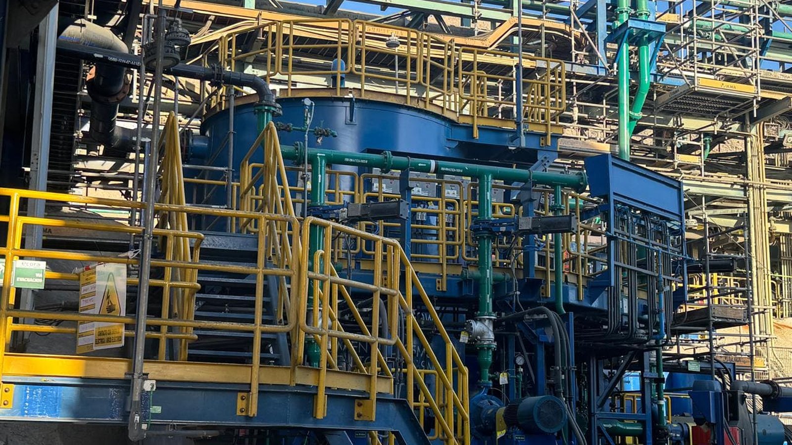
One location, three stages: scan, model and site.
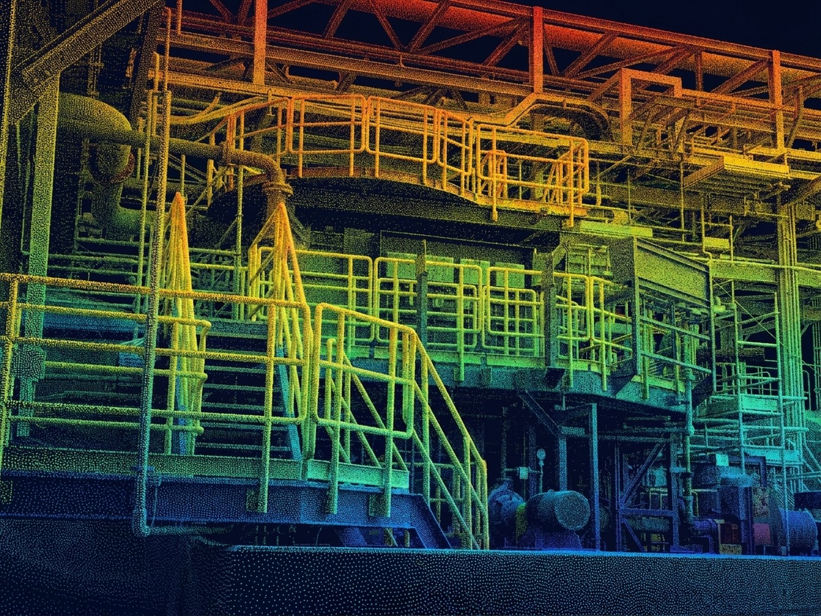
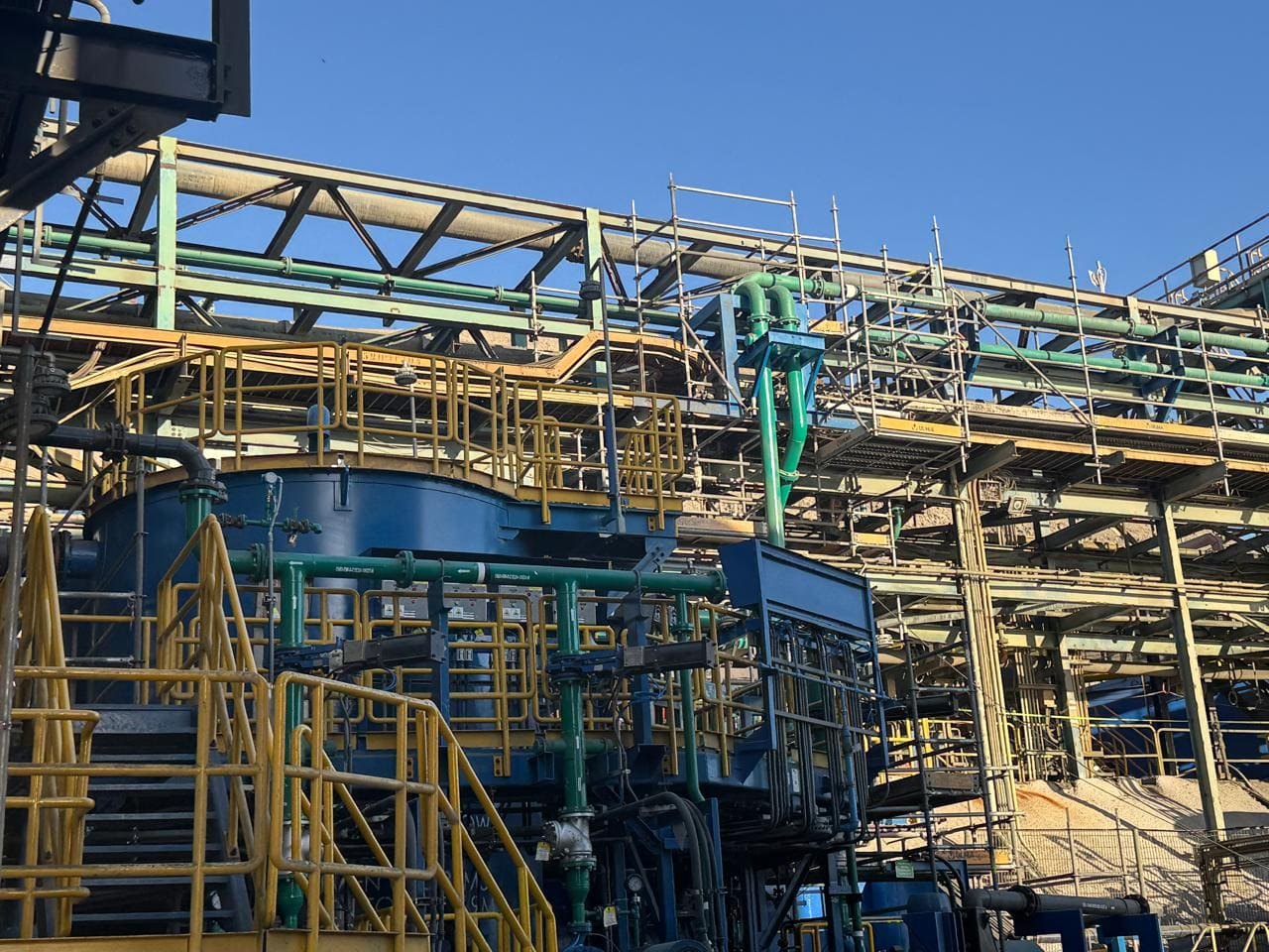
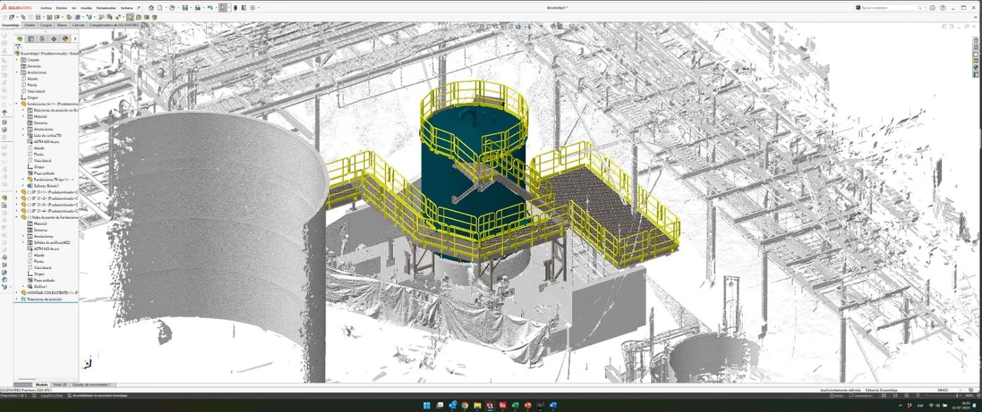
Drag the handles to walk through the three stages. First the point cloud of the original scan — before fabrication, with no tank and no process piping; then the 3D engineering model built on that site; and finally how it ended up installed. Same framing in all three.
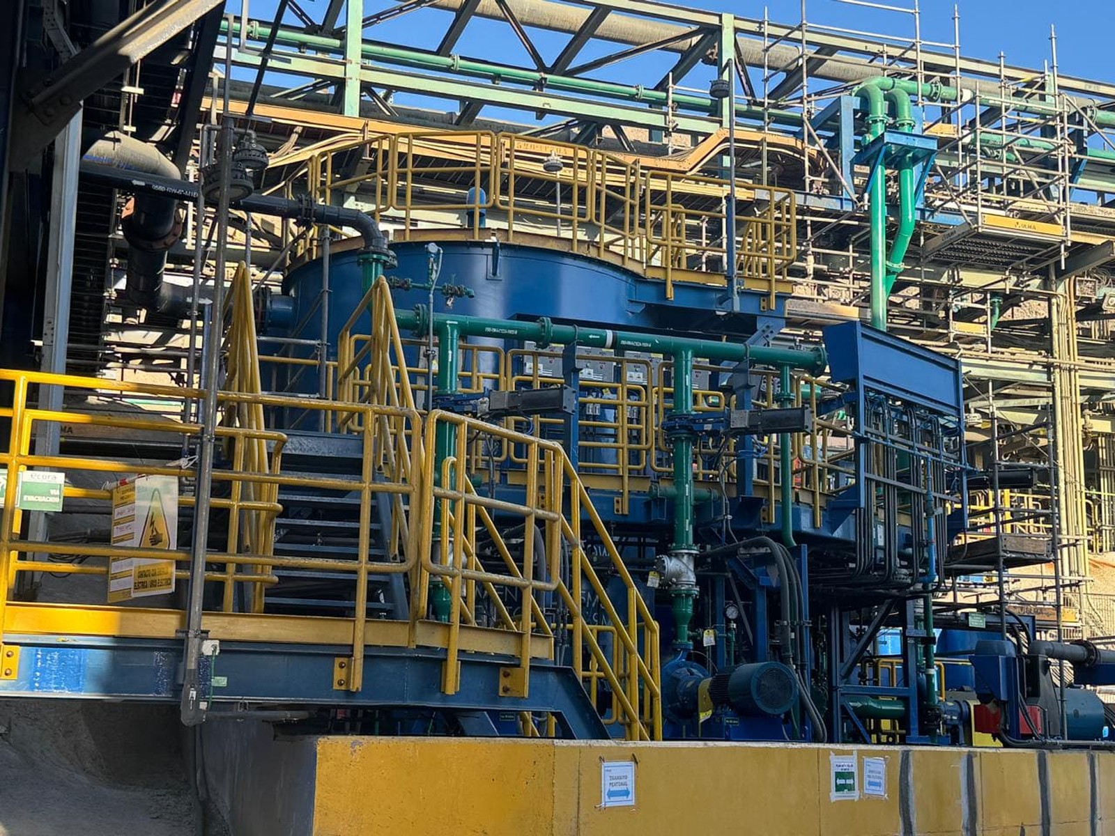
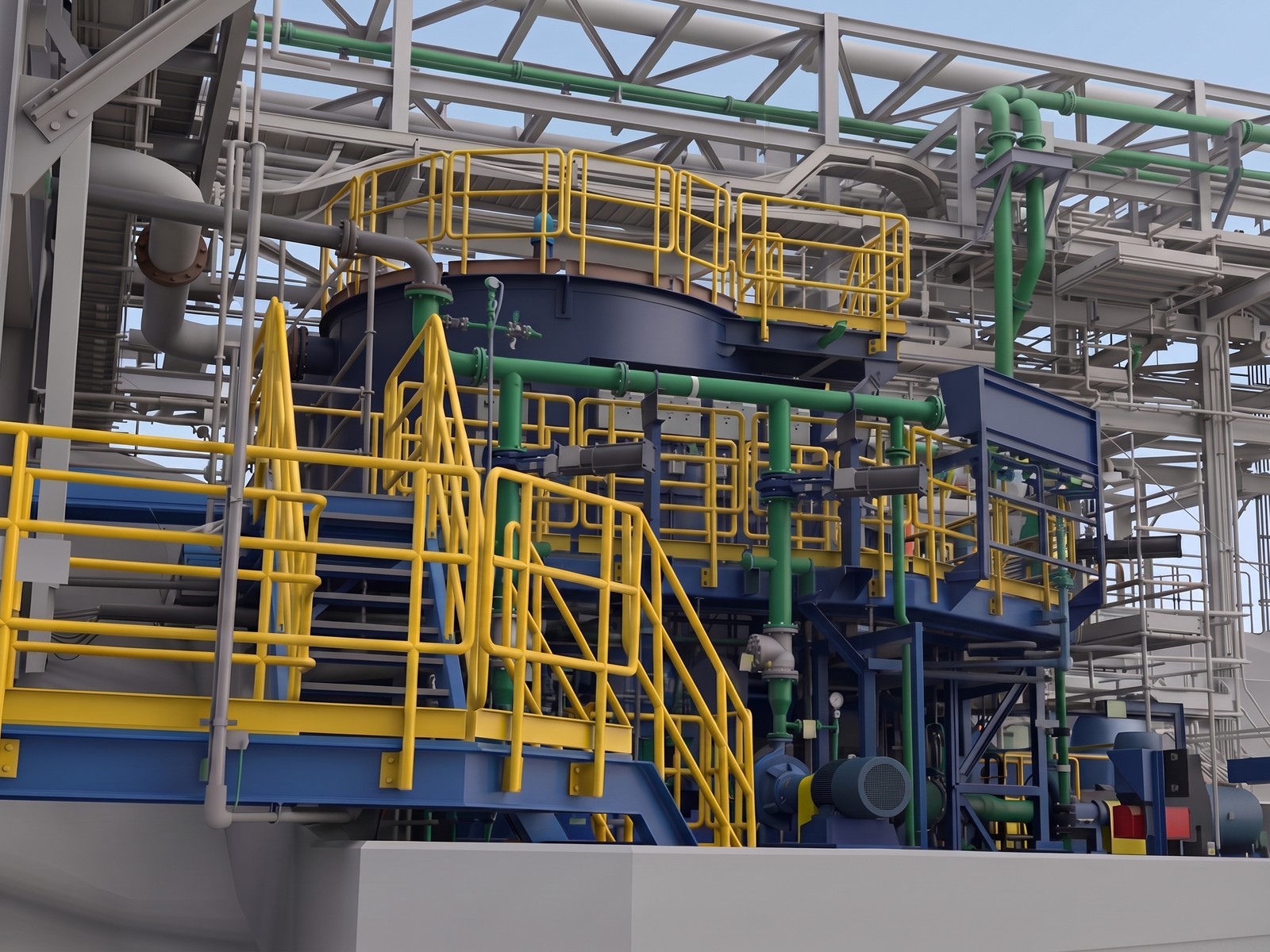
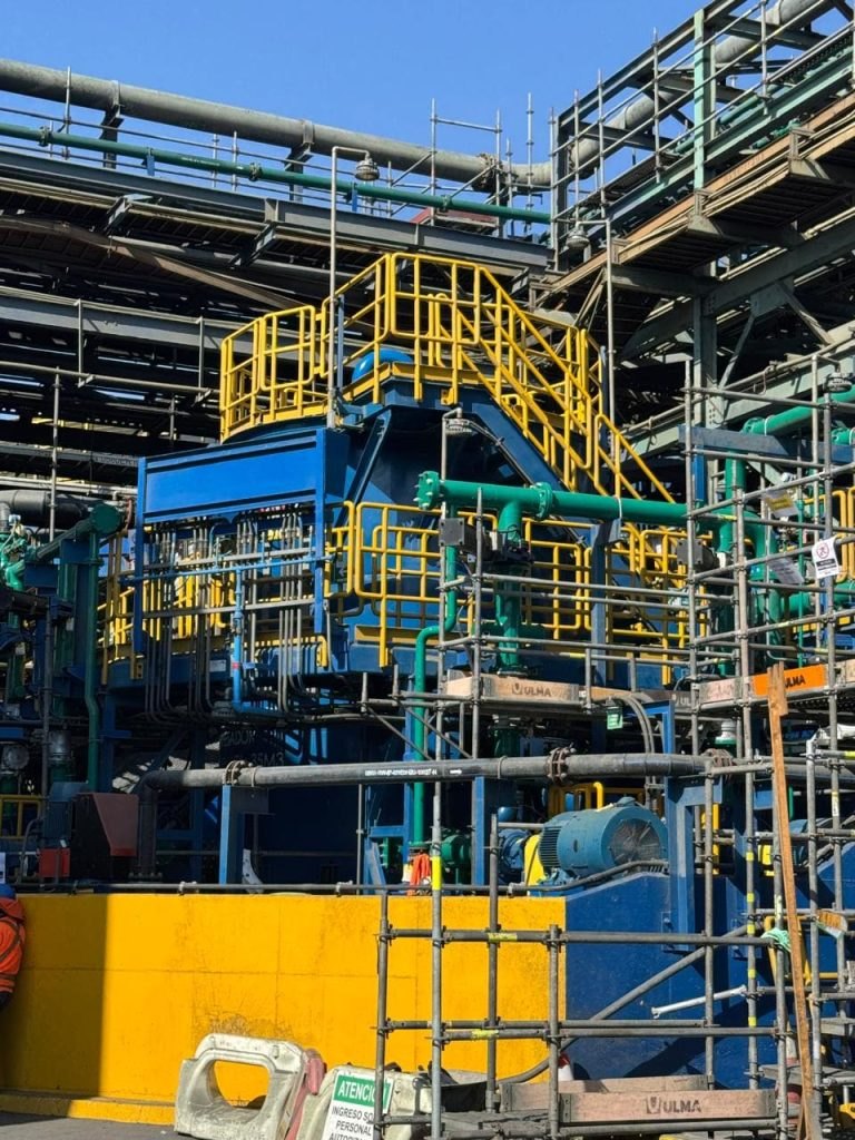
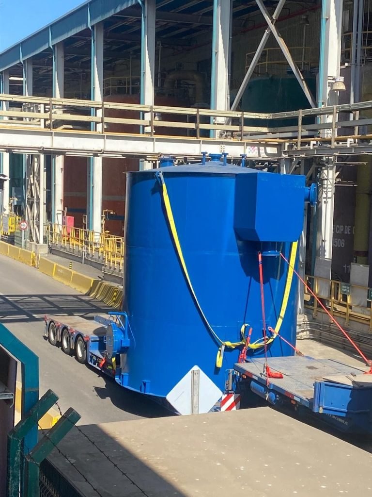
A treated-water tank, all its process piping and the supports that hold it — built from a scan of the site, because there was not a centimetre to spare.
Work started with a direct field survey: we modelled the existing installation in 3D, validated drawings and redesigned the ducting so every line fitted without interferences. Verification relied on augmented reality software, overlaying the model on the real ground to catch clashes before a single piece was made.
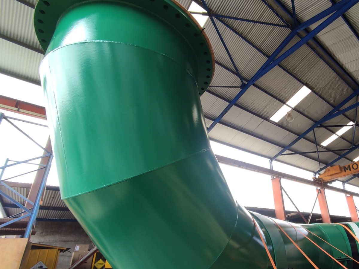
CGK's scope covered the access platforms and handrails, the entire process piping — the green lines running through the assembly — and the tank with its top handrails. All of it came out of our workshop and was installed on site with full support.
Because the model was built on the site itself, what was delivered matches what was modelled. The slider above shows it with no tricks: it starts from the point cloud of the original scan — when the tank and piping did not yet exist — moves to the 3D engineering model and ends at the working installation. Same framing in all three stages.
Tank assembly with water lines and platforms · captured on site
This is what the installed tank looked like, back when it did not exist
This is the verification the description mentions, recorded exactly as it happened. With Trimble SiteVision the complete IFC model — the tank, all the process piping and the access platforms — was overlaid at 1:1 scale on the civil works already built.
Walking around the assembly, we checked that every line came in where it should and that the platforms left the accesses clear. The corrections were made in the model, where they cost hours instead of weeks.
- Complete IFC model over the real structure
- Interferences caught before cutting plate
- Accesses and platforms checked on site
The same check, filmed from behind
What is on the screen and what is around it
The video above is the iPad recording. This one was filmed by a colleague from behind, which is why it shows both things at once: on the screen, the ducting and structures from the model; around it, the concrete foundation with its anchor bolts, the scaffolding and the plant running.
As the crew moves, the model stays fixed to the ground. That is where you see how each line comes in and how much room is left to install it, months before the first piece exists.
Other projects
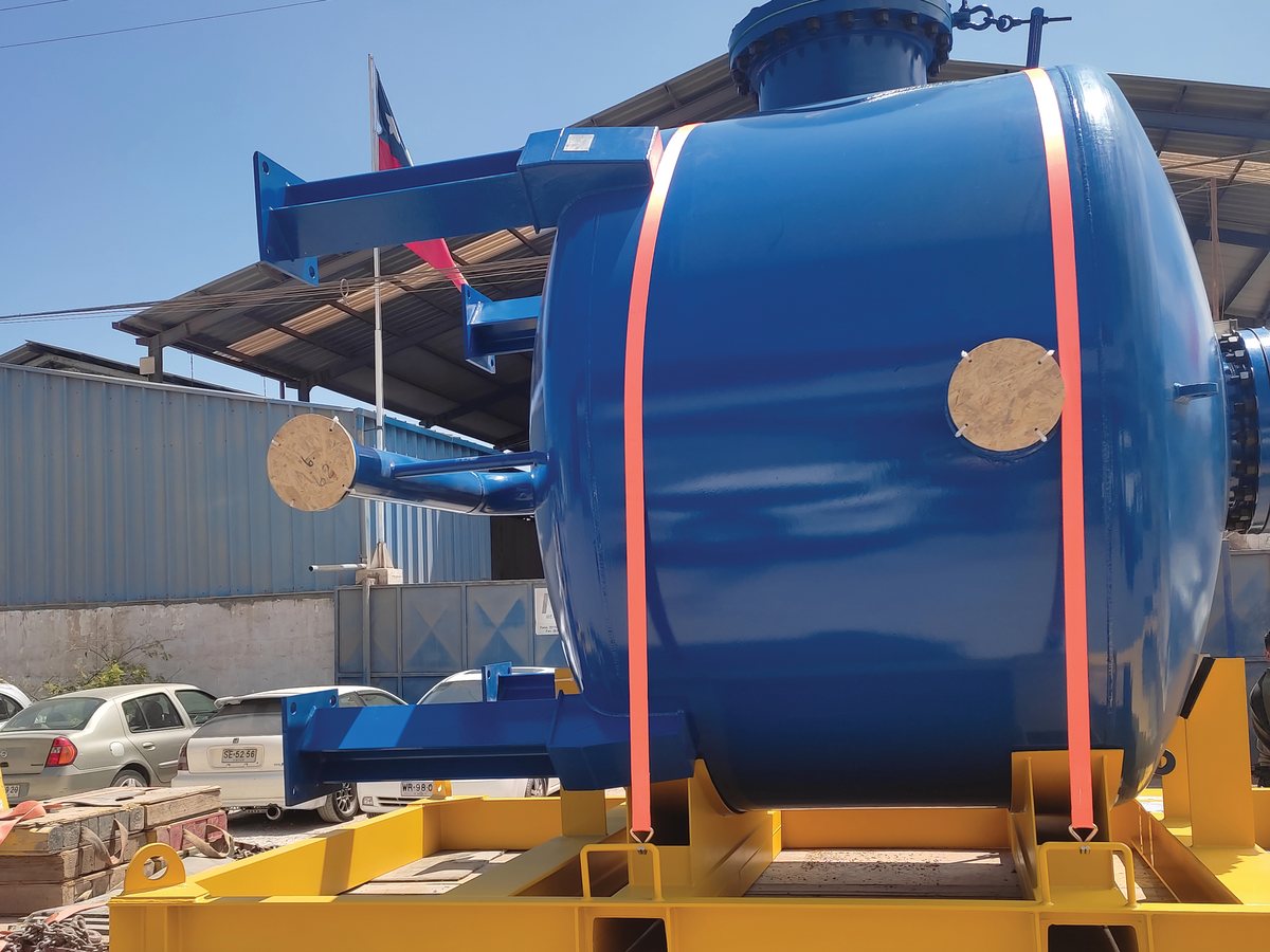
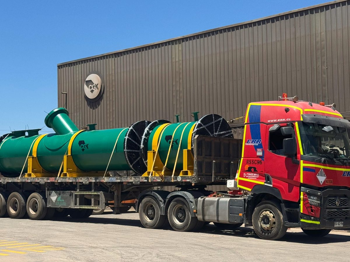
Tanks, large-diameter ducting and reverse engineering — where the 3D model has to fit what is already on site.
Need to model an existing installation and build onto it?
Field survey, augmented reality verification and fabrication under one roof. Tell us what has to be modified.