

Gates that operate themselves — and nobody gets exposed
One mechanism, three stages: scan, model and installation in the plant.
Drag the handles to walk through the transition — from the survey of the existing chute to the 3D model of the mechanism, and from the model to the real system installed under the concrete slab.
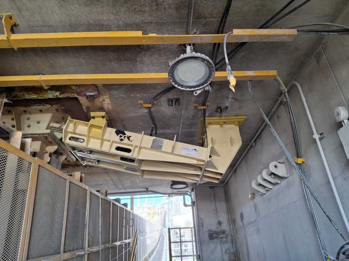
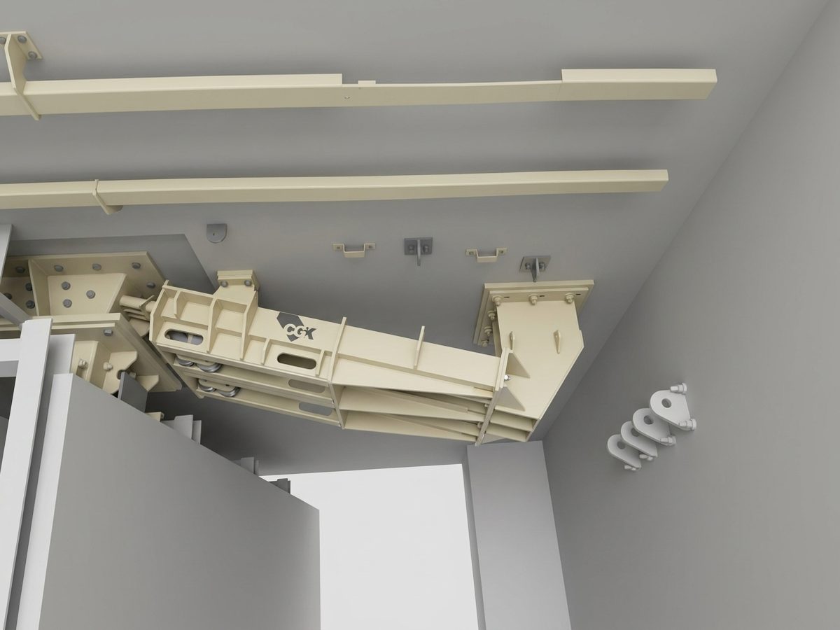
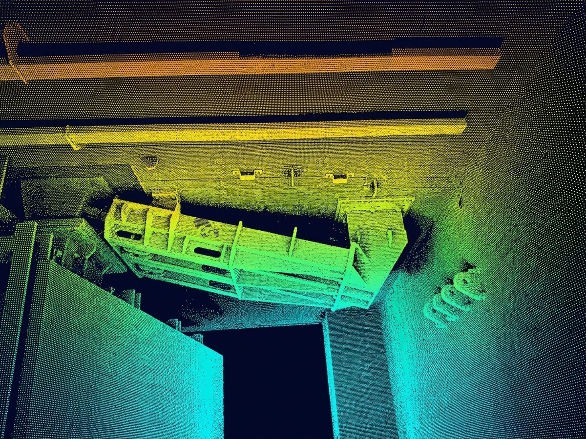
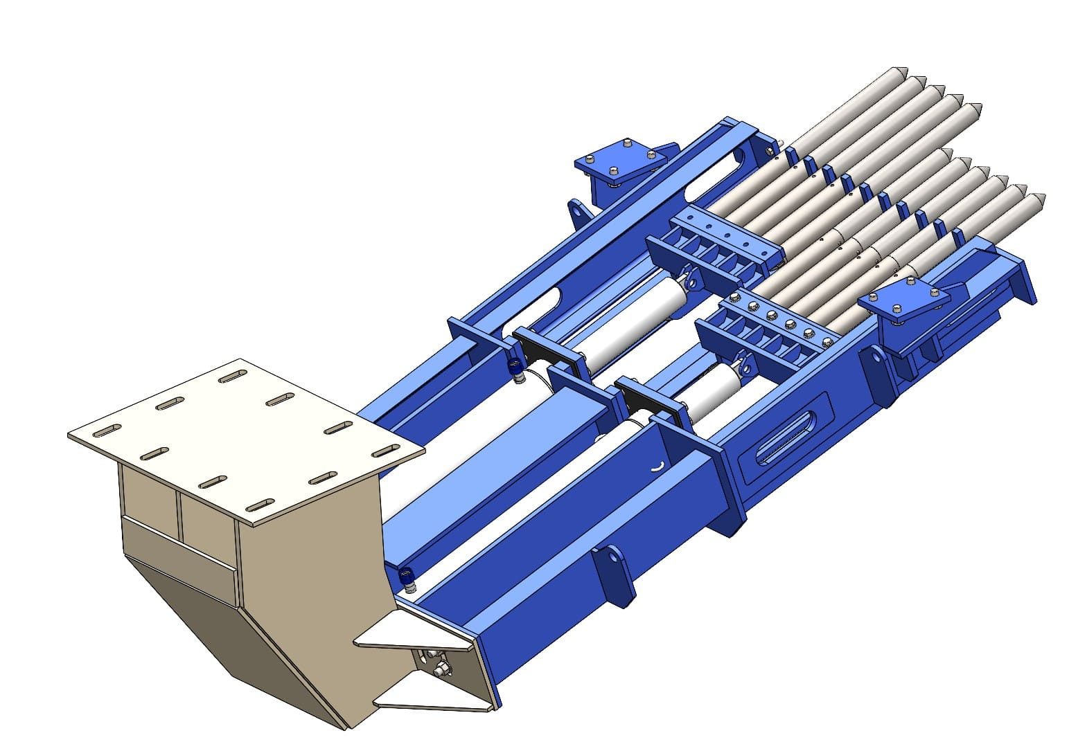
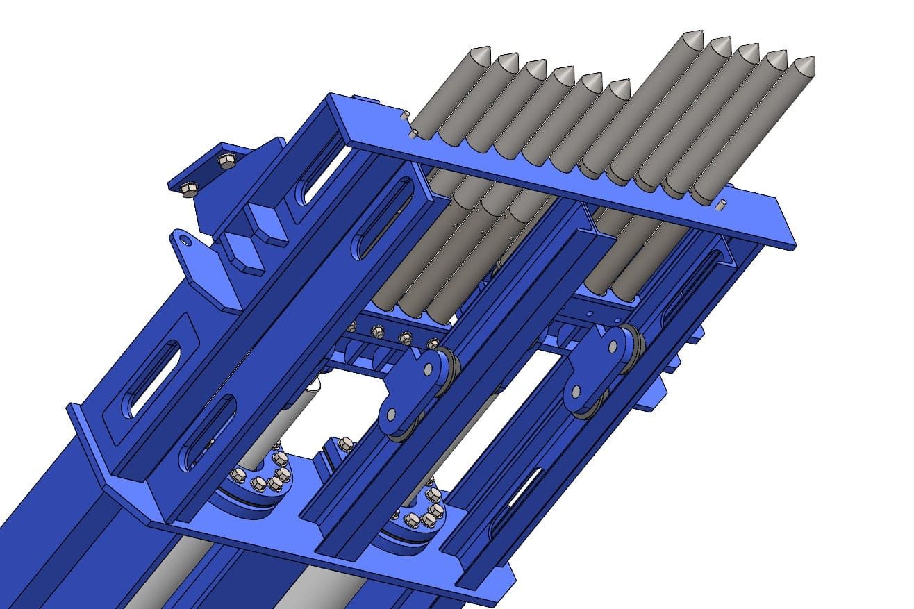
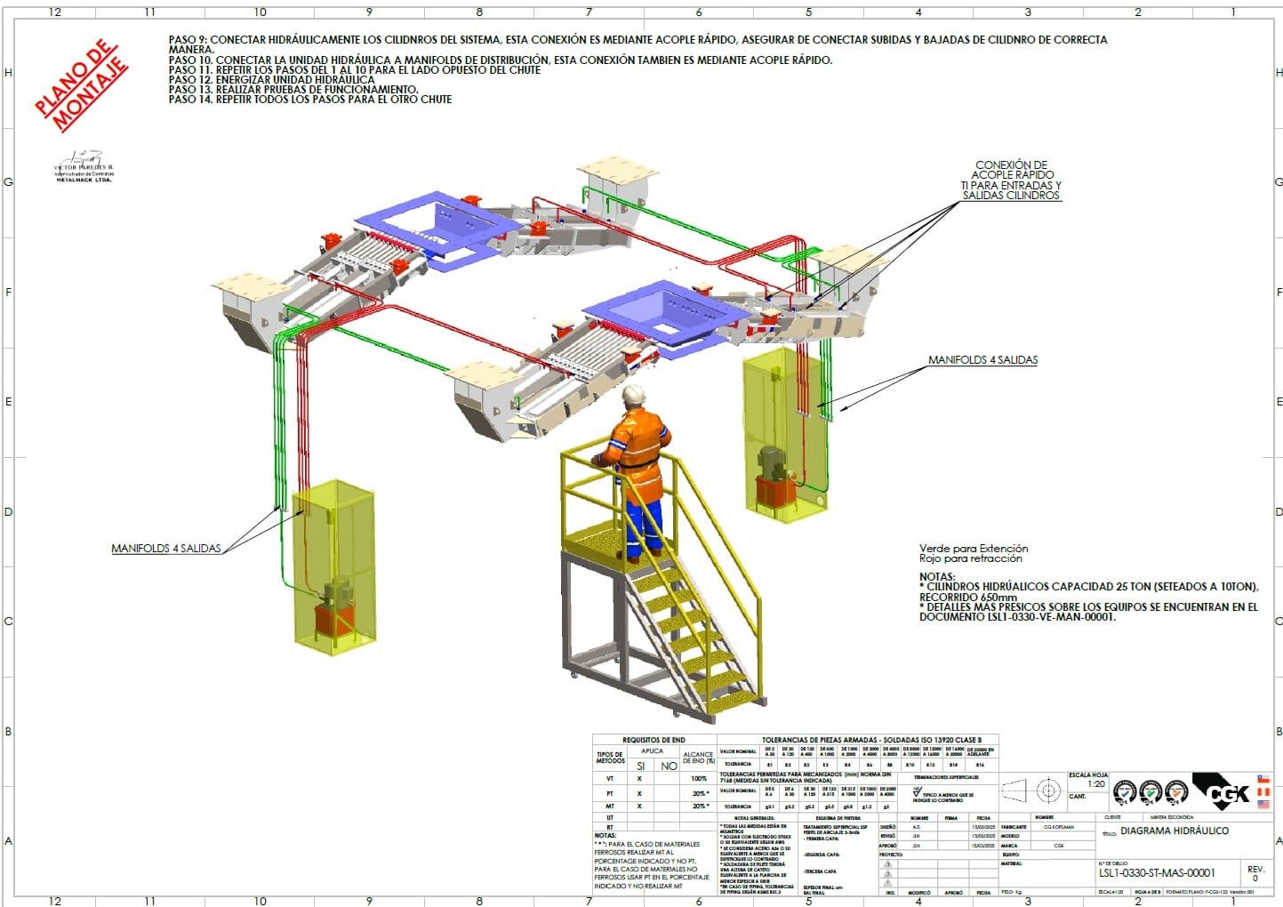
The cylinders push the gates and close the chute.
Render of the 3D model in operation. When the hydraulic cylinders are actuated, the rods extend and push the two banks of gates from both sides until they meet in the middle of the chute — from fully open to fully closed. The mechanism is shown on loop. All commanded remotely, with nobody nearby.
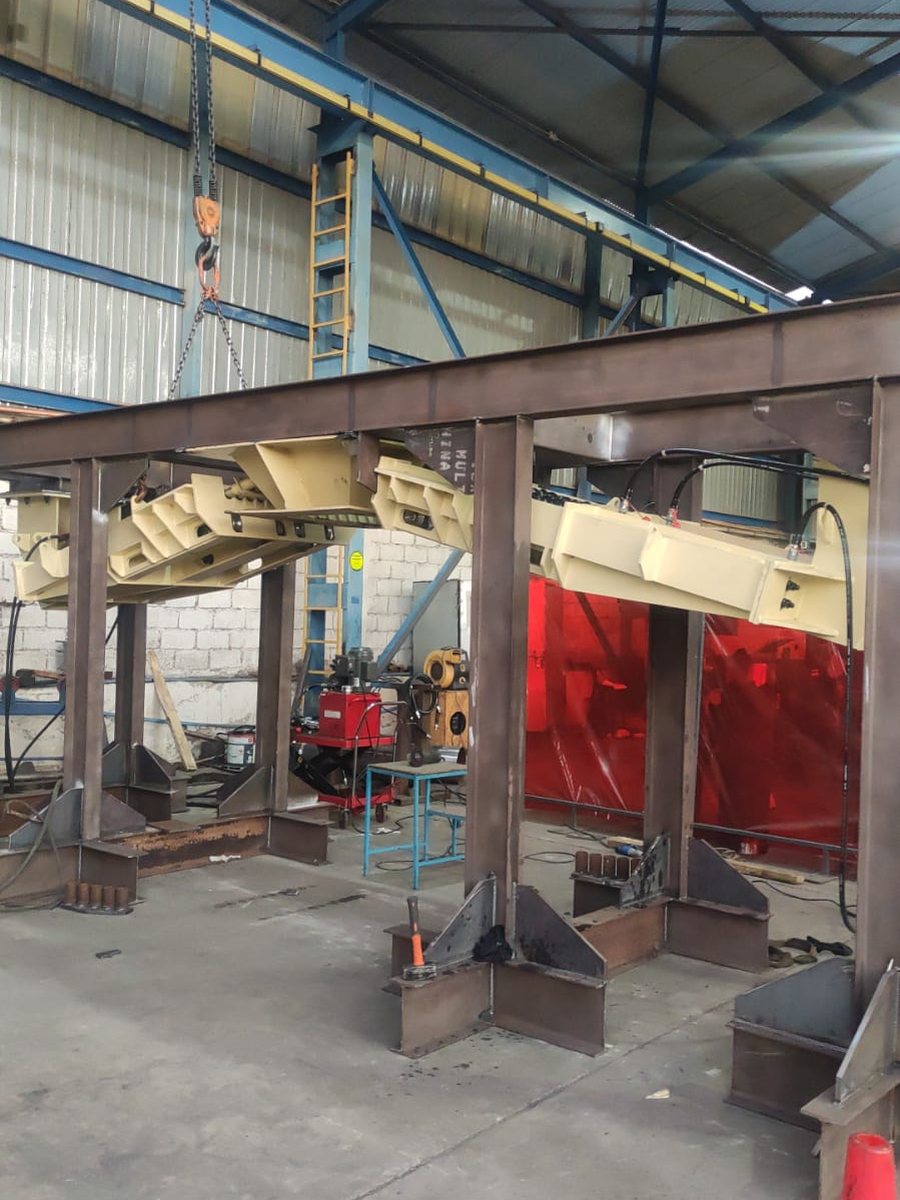
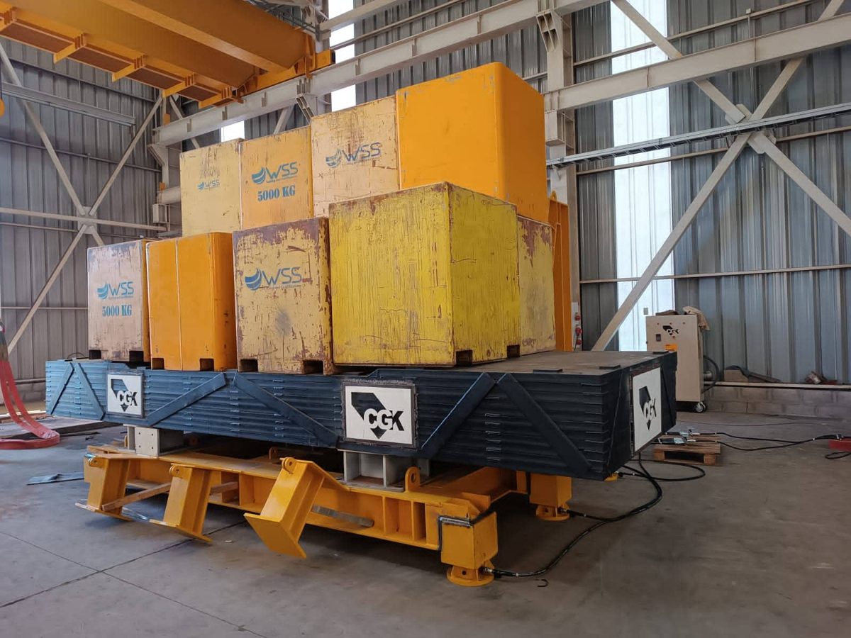
Chute on the test rig · CGK workshop
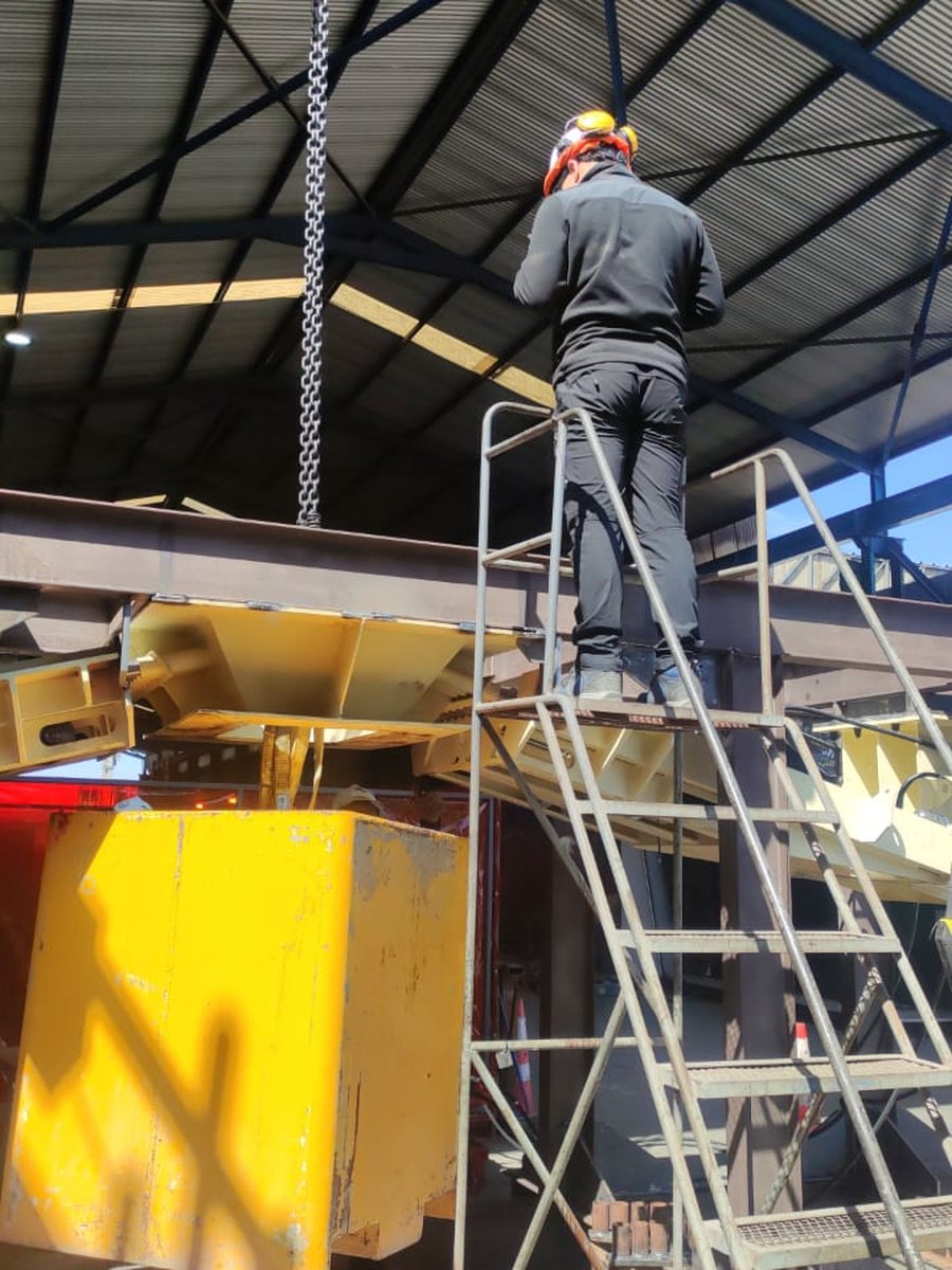
The rig was built in mid-air first
To test the mechanism unloaded, the whole chute had to be mounted on a rig in the workshop. Before welding the first support, the model was overlaid with Trimble SiteVision on the chosen spot, at 1:1 scale.
With the real structure, the overhead crane and the crew all in the same frame, we confirmed the working height, the position of the supports and the clearance needed to operate the gates and for the rods to travel.
- Mounting height and support positions
- Clearance for operation and for people
- Travel of the gates inside the chute
The mechanism did not have its debut at the mine.
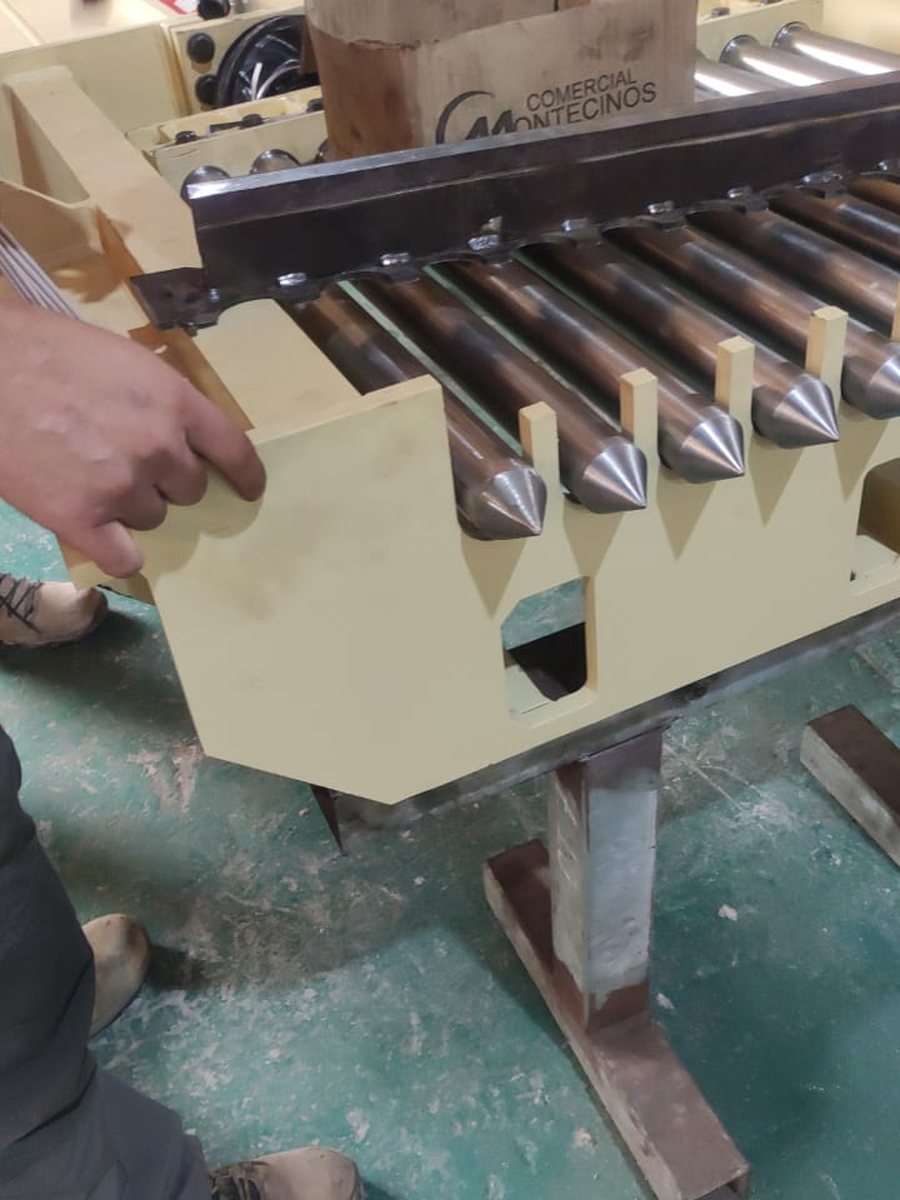
We built a test rig in our workshop reproducing the chute geometry: a steel frame with the two banks of gates mounted facing each other, fed by a portable hydraulic power pack. There the system was cycled, adjusted and loaded — with the client present — until there was nothing left to tune on site.
Operate remotely and hold the weight
The two things that had to be proven before going up to the plant: that the gates close and open by remote control, with nobody near the mechanism, and that when closed they hold the load that is going to fall on them.
Retention was tested with counterweights suspended over the closed mechanism, repeating the cycle until the behaviour of rods, bushings and anchors was verified. What you fix on the rig is not something you have to fix hanging under a chute.
- Test frame replicating the chute geometry
- Portable hydraulic power pack and remote actuation
- Full open ⇄ closed cycling under load
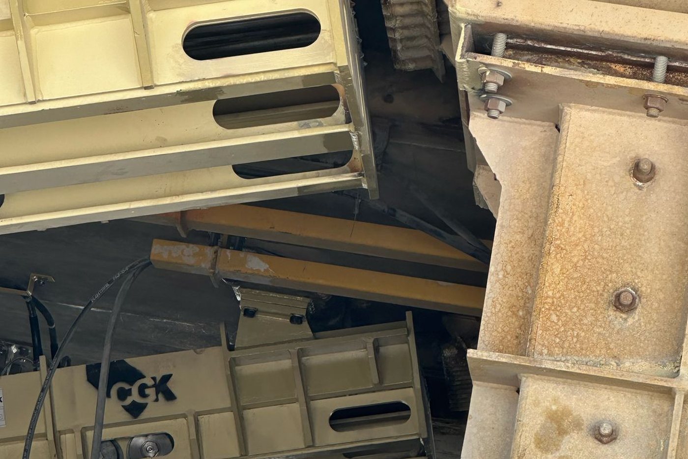
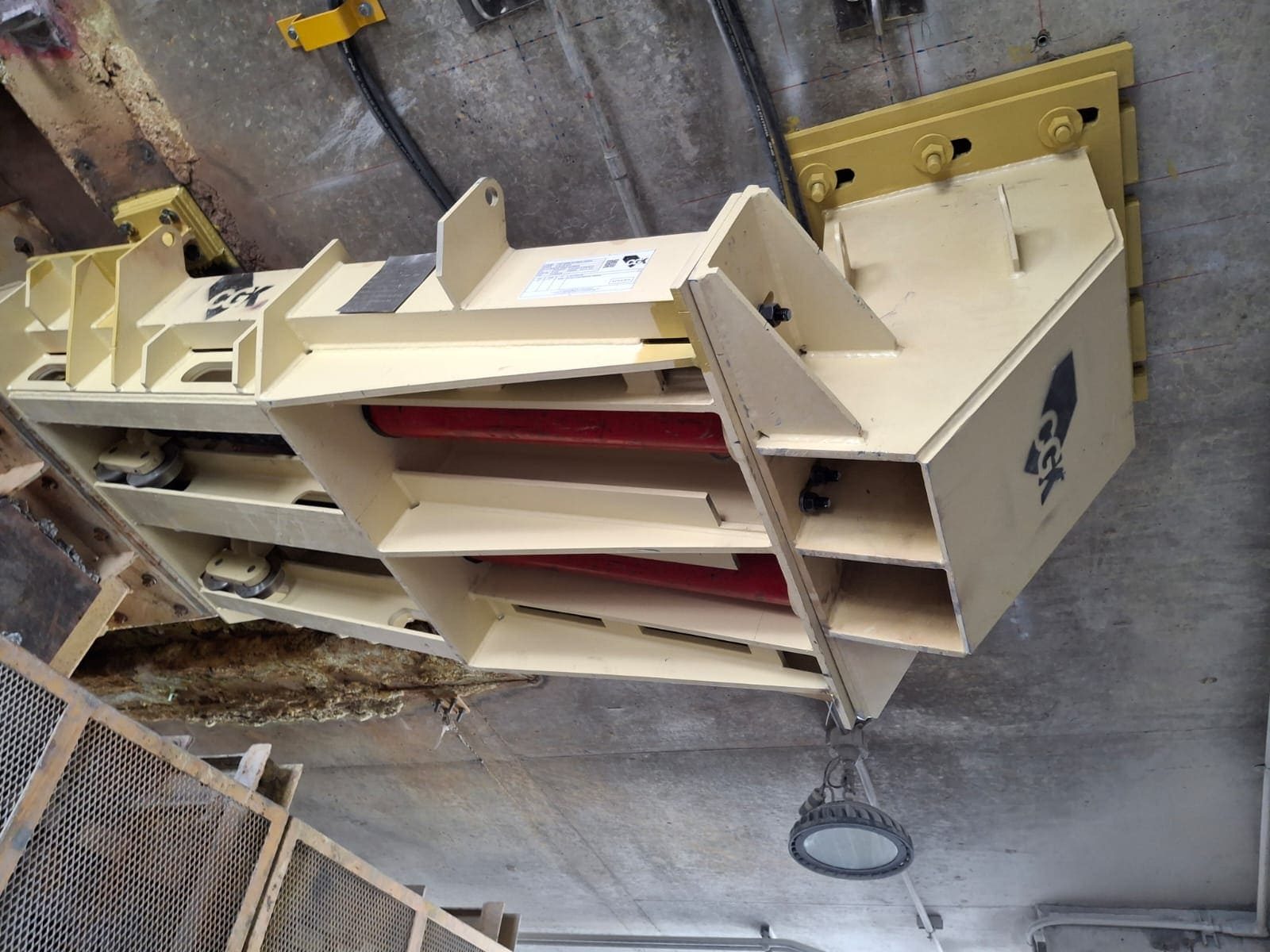
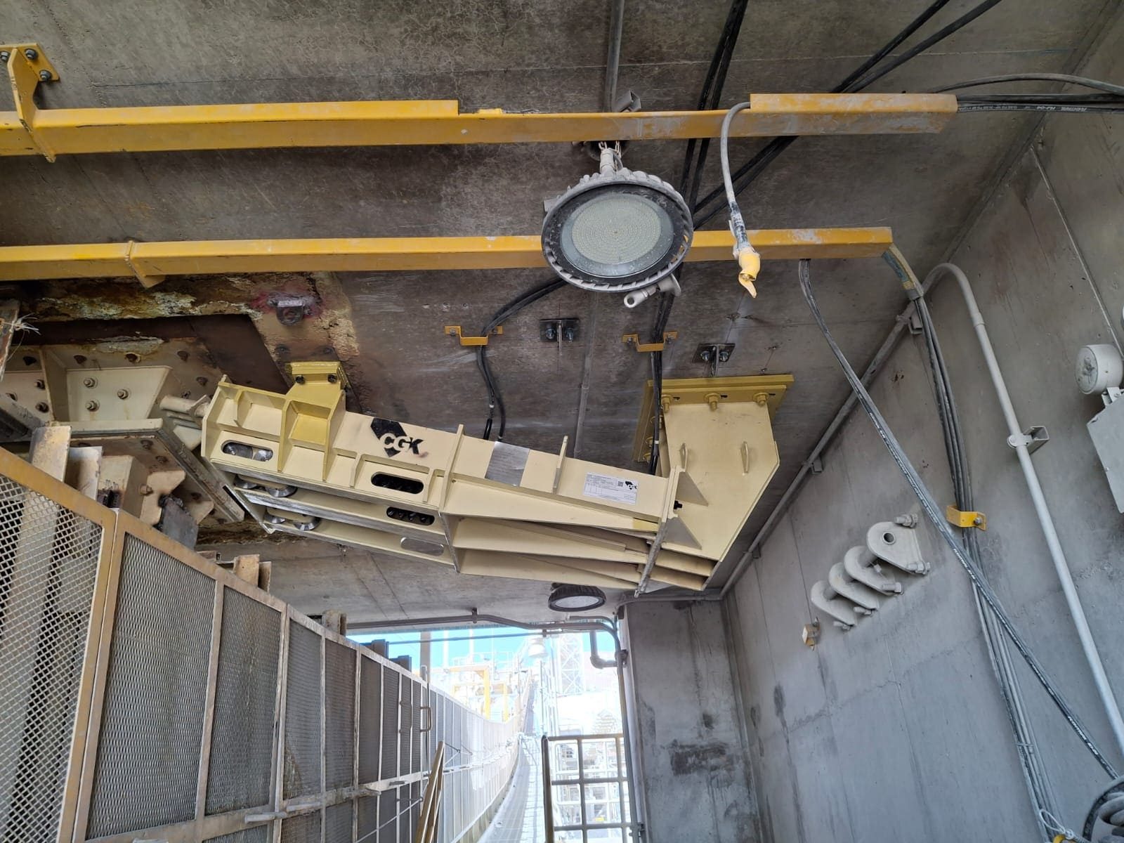
This is how it ended up installed under the chute.
Both banks of gates in their final position, bolted to the existing structure and connected to the hydraulic line. Since they went in, closing the chute no longer requires anyone to approach: it is operated from a distance and the ore stops on the tips.
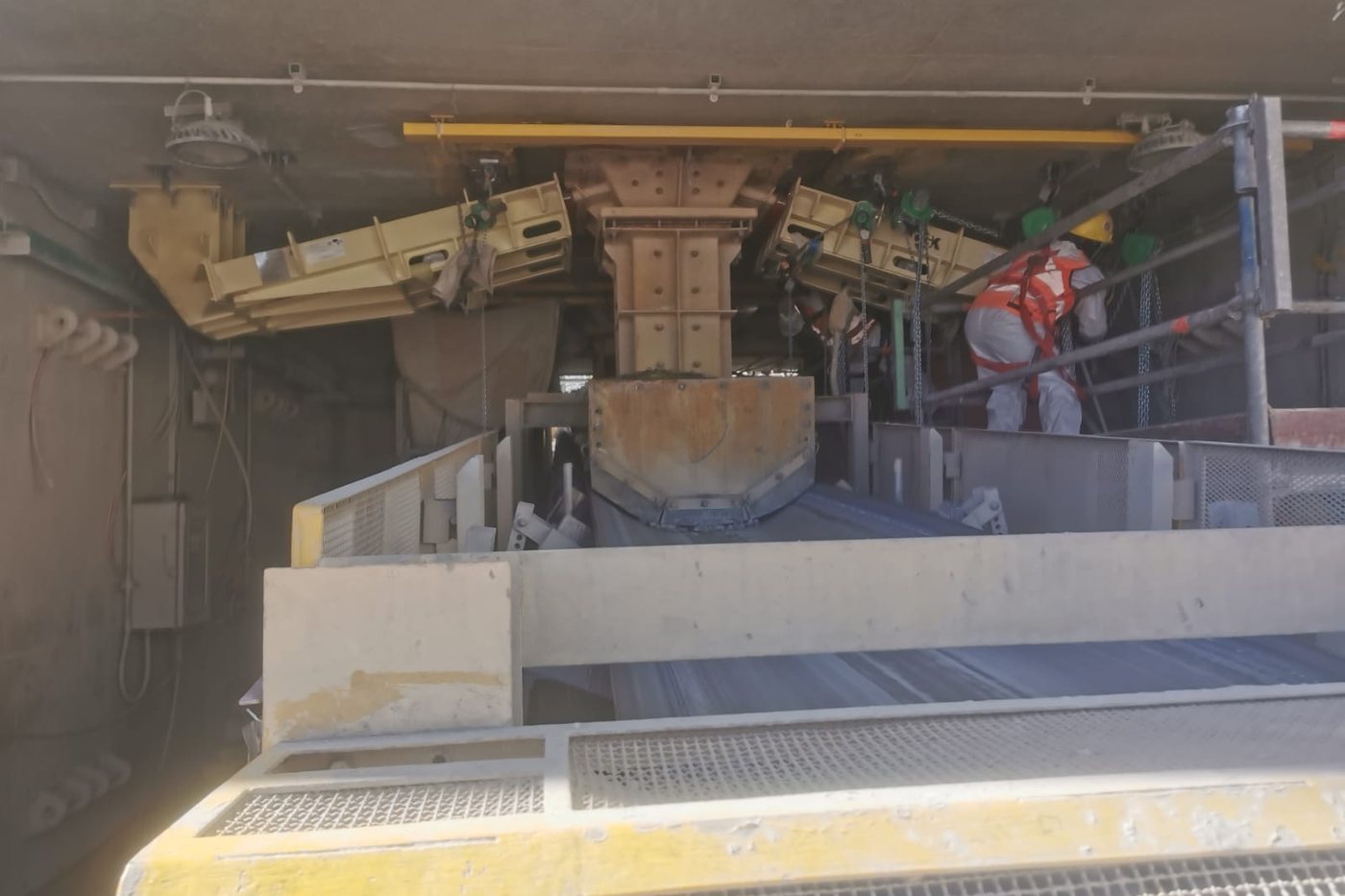
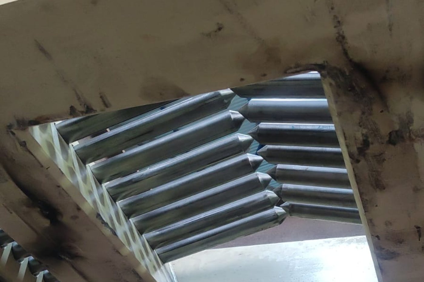
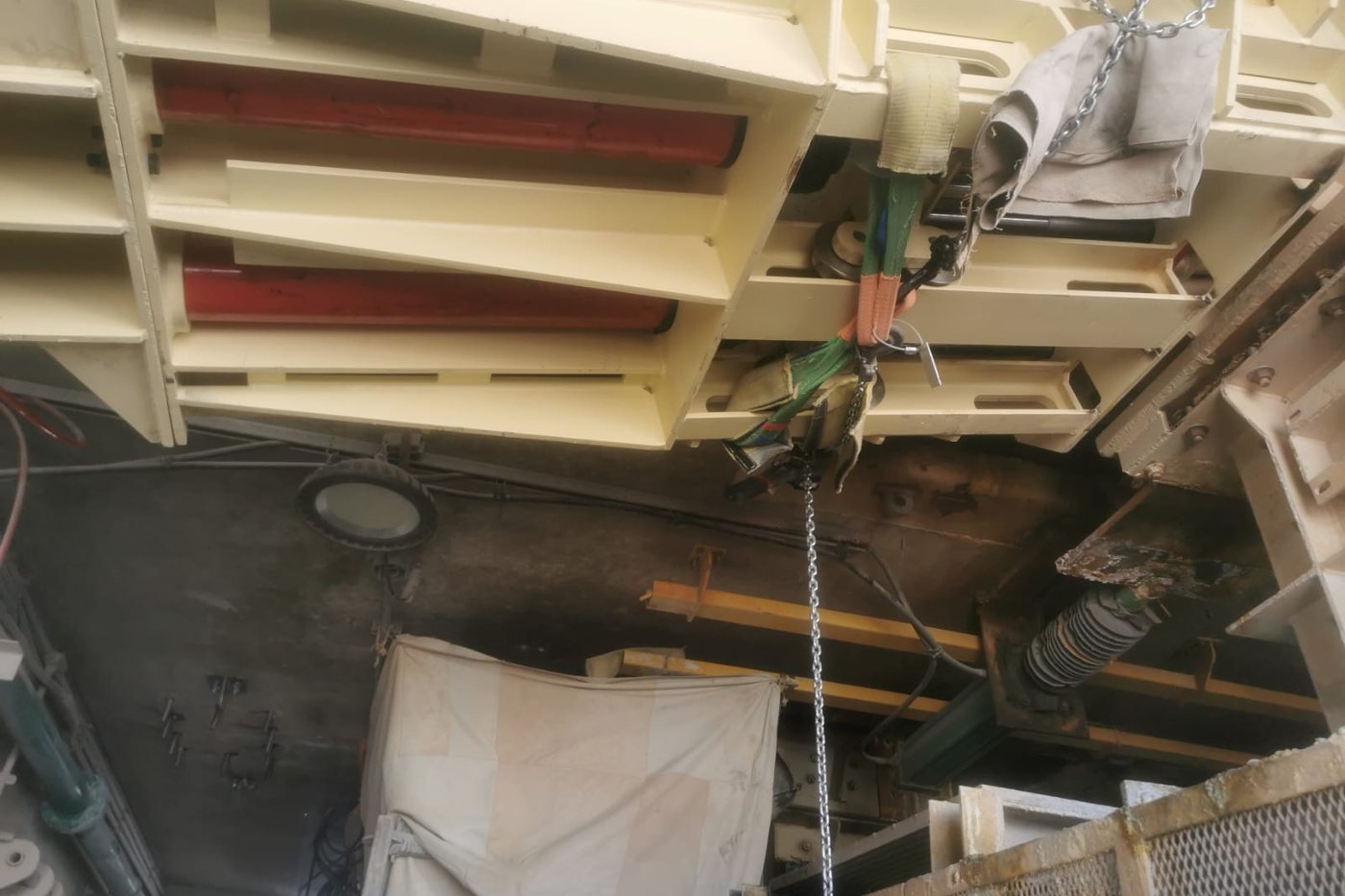
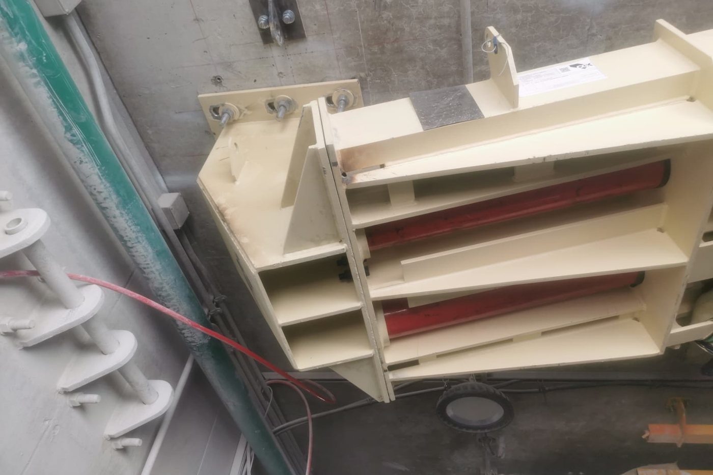
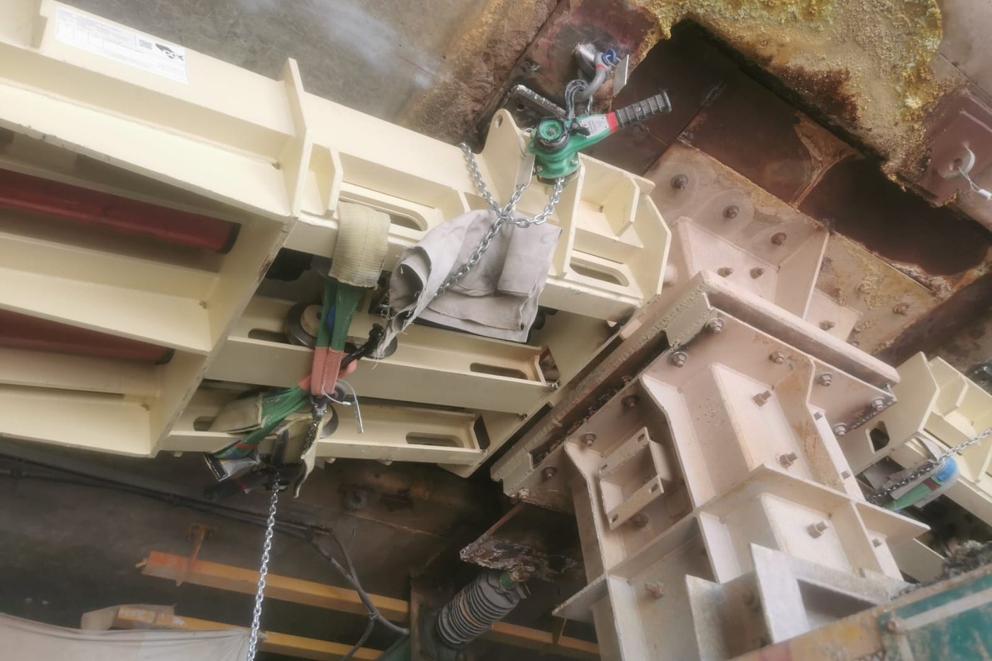
A pencil-gate system with hydraulic actuation and remote operation: the goal was to eliminate person-equipment interaction at the chute.
The project started with a field survey of the chute and its surroundings. On that basis we iterated the engineering proposal with the client, backing every version with FEM structural analysis and DEM analysis of the material flow — because a gate holding back rock works under loads you calculate, not guess.
Before reaching site, the complete system was tested at the works on a test rig that reproduced real operating conditions: remote actuation and load retention, cycled until the settings were locked in. Only then came validation in the plant, installation support and operating tests on site, with full accompaniment throughout the project.
The result is installed and running under the chute: a mechanism operated from a distance, with nobody having to go near it — safety by design, not by procedure.
Other projects
More cases with the same transition: point cloud, 3D model and real component.
Is there a job in your plant where people are still exposed?
We design remotely operated mechanisms, calculate them with FEM and DEM, and test them on a rig before they reach site. Tell us the problem.